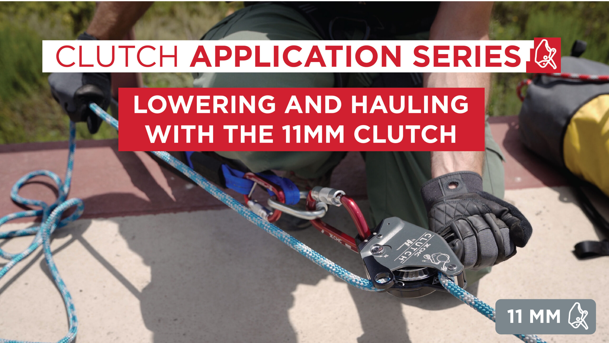
CLUTCH 11mm Lowering & Hauling
This CLUTCH application video covers lowering and hauling with the 11mm CLUTCH. We begin by demonstrating single line methods and progress to Twin Tension Rope Systems (TTRS) in mirrored and nested double CLUTCH configurations. Combining the CLUTCH with CMC’s G11 Lifeline creates 11mm NFPA G-Rated systems that save weight and reduce volume, ideal for any rescue or training operation. Always use a backup when training or working on rope.
00:20 – Overview
01:05 – Anchor Systems
01:30 – Twin Tension Lowering
02:58 – Double CLUTCH TTRS
03:20 – Tying Off the CLUTCH
03:49 – Single Line Hauling
05:18 – Hauling TTRS
**Full Transcript Below**
The CMC CLUTCH™ BY Harken Industrial™ is the latest evolution in rescue and rope access hardware. Suited to a multitude of rigging operations, the CLUTCH moves seamlessly between anchor-based systems and personal use.
Hi I’m John McKently. I’m the director of the CMC Rescue School.
For this video, we will focus on the CLUTCH being used in anchor-based systems for lowering and hauling.
We will begin by demonstrating how to setup and operate a twin tension lowering system, including a brief review of the Double CLUTCH TTRS. Once lowering is complete, we will discuss how to transition to hauling. We will show hauling on a single line with a belay and hauling in a twin tension system.
Both the 11mm gray CLUTCH and 13mm red CLUTCH function the same in this scenario, the primary difference between them being rope diameter compatibility. In this video, we complete each task with the 11mm gray CLUTCH.
To prepare for a lowering/hauling operation, build solid anchors in accordance with department policies and regulatory guidelines. The anchors in this video are provided by a fire training facility and are intended for demonstration purposes only. When in the field, sufficient anchors may include a nosed-in truck, adequately sized tree, approved picket system, or other natural or artificial anchors.
Here we’ve created two anchor stations, one for each rope in the Twin Tension Rope System.
Begin by attaching a CLUTCH to the anchor at each station. Load and function test the CLUTCH to confirm proper operation.
Each CLUTCH operator should stand slightly behind the CLUTCH, between the device and the anchor, to easily manipulate the rope tail and the control handle, while keeping a visual on the rope ends, the edge, and the opposing anchor station.
Attach the working end of each rope to the load, refer to established practices for approved methods. Gradually weight the ropes and adjust tension between both CLUTCH devices until the weight is shared between them.
When the team is ready, the two CLUTCH operators can begin to lower in unison with shared tension between the lines.
Lowering with the CLUTCH is accomplished by gripping the rope tail while moving the handle into the RELEASE range. The speed can be modulated by the position of the handle and the angle of the rope tail as it feeds through the device.
The CLUTCH operators should watch each other and communicate throughout the lower with the goal of matching descent speeds and sharing the load as evenly as possible.
The acceptable descent speed depends on the weight of the load. For loads between 30kg and 200kg, limit the speed below 2 meters per second. For loads over 200kg, limit the speed to below ½ meters per second.
If anchoring is appropriate and gear is available, these separate CLUTCH stations can be combined into one using the Double CLUTCH technique. In this approach, CLUTCH units are rigged so they can be controlled by a single operator for better shared tension using fewer personnel. See our Double CLUTCH application video for more information.
When lowering is complete, rotate the handle to STANDBY for short-term inactivity, or rotate the handle to STOP for added security, this locks the rope in place and tucks the handle out of the way. Consider tying-off the CLUTCH if leaving it unattended.
Pass the rope tail through the carabiner, tie it around the tension side of the rope with an overhand knot located at least six inches from the device.
We will now address how to haul with the CLUTCH using a single line with a belay as well as with a TTRS. We will demonstrate a 3:1 and show how it can be quickly converted to a 5:1 using the integrated becket with the CLUTCH.
Desired mechanical advantage depends on the weight of the load, available personnel and size of the haul field.
To transition from lowering to hauling, build a mechanical advantage system on one of the twin tension lines.
Begin by tying a prusik on the tensioned rope and attach a pulley.
Run the rope tail from the CLUTCH through the pulley and back towards the anchor.
This can be further redirected with additional pulleys to suit the given haul field.
Rotate the handle to STANDBY for highest efficiency. When all team members are ready, begin pulling the slack end of the haul line.
As the haul line is pulled in, the opposing CLUTCH operator pulls in slack to maintain tension on the belay line.
When the pulley reaches the anchor, the system will need to be reset. Release the tail end of the haul line and pull the prusik and pulley back towards the load.
The auto-locking progress capture feature of the CLUTCH allows hands-free reset of mechanical advantage systems and easy stop/start operations to communicate or resolve issues.
Remember to only use only single sheave pulleys in the 3:1 as it is damaging and dangerous to load just one side of a double sheave pulley.
To build a hauling TTRS where the load is shared, install identical mechanical advantage systems on each haul line and raise the lines in tandem. Consider redirecting the rope tails so they can be hauled together for equal pacing and tension. TTRS reduces the risks involved with a main line failure.
To convert to a 5:1, lay the rope tail in a Z pattern running from the prusik pulley to the CLUTCH and back to the prusik. Replace the single pulley with a double pulley and load the rope from the two bends created by the Z pattern.
Next, attach the single pulley to the CLUTCH becket and load the rope from the bend created by the Z pattern. The 5:1 is now ready to haul.
Any pulleys used on the becket should have a swivel to avoid torsional forces.
Additional mechanical advantages can be created using more pulleys or piggyback systems.
Refer to the CLUTCH manual and the CMC website for additional information. Please contact us if you have any questions about the CLUTCH.