Pulleys and Mechanical Advantage Systems
Raising systems are essential in any rescue or rigging scenario in which loads are lifted using rope. A raising system using a combination of pulleys to leverage the force applied in lifting is referred to as a mechanical advantage (M/A) system. Whether building a simple, compound, or complex M/A system, it’s important to first understand how pulleys operate.
How Pulleys Work
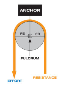
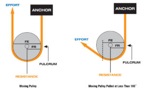
A fixed pulley can be viewed as a first-class lever. The fulcrum is located at the axle in the center of the sheave, directly below the carabiner that connects the pulley to the anchor point. Because the sheave is round, the distance (FR) from the axle (fulcrum) to the point the rope leaves the sheave and goes to the resistance (load) is equal to the distance (FE) from the axle to the point that the rope leaves the sheave and goes to the effort (force). The two lever arms are equal, resulting in 1:1 MA and the reason a change-of-direction pulley does not increase the mechanical advantage of the system.
A moving pulley can be viewed as a second-class lever. The fulcrum is located on the edge of the sheave directly below the point where the rope is attached to the anchor. One lever arm (FR) extends from the fulcrum to the pin, which is directly above the carabiner that attaches the resistance (load) to the pulley. The other lever arm (FE) extends from the fulcrum to the point where the rope leaves the sheave and goes to the effort (force). This lever arm is twice as long as the other arm, resulting in 2:1 MA. Moving pulleys increase the mechanical advantage of the system.
Pulleys in Mechanical Advantage Systems
Pulleys perform two distinct functions in mechanical advantage systems. If the pulley is attached to the anchor, it is called a fixed or change of direction pulley. Its job is to change the direction of pull on the rope. If the pulley is attached to the load, it is a movable or mechanical advantage pulley. Its job is to increase the mechanical advantage of the system.
A ratchet, also called a progress capture device or PCD, is a device that, when attached to an anchor, will hold the rope so that the load will not lower back down when the pulling force is released. This acts as a safety so the load will not fall back down if the haul team lets go of the rope. This also allows us to reset the mechanical advantage pulleys so we can haul the load further. The number of times that a raising system will need to be reset will depend on the distance the load must be raised and the distance the raising system can be extended. A mechanical rope grab, or a friction knot tied with a prusik loop can be used as a ratchet.
By building systems using different combinations of mechanical advantage pulleys, change of direction pulleys, rope, anchors and ratchets, we can come up with the right tool for the specific job we need to accomplish. Generally, using the lowest mechanical advantage needed to get the job done will result in the quickest rescue because it requires fewer resets.
For simplicity, this blog we will ignore the friction inherent in these systems and focus on theoretical mechanical advantage. Theoretical vs. Actual Mechanical Advantage will be covered in future blogs.
Simple Pulley Systems
Simple M/A systems can be defined as systems with all the moving pulleys moving in the same direction and at the same speed as the load. A few simple pulley systems are most frequently used. The most common is a 3:1 mechanical advantage, sometimes called a “Z” rig because when rigged, the rope looks like a “Z”. In theory, a 100-pound pull would raise a 300-pound load. Due to friction, the actual mechanical advantage is slightly lower.
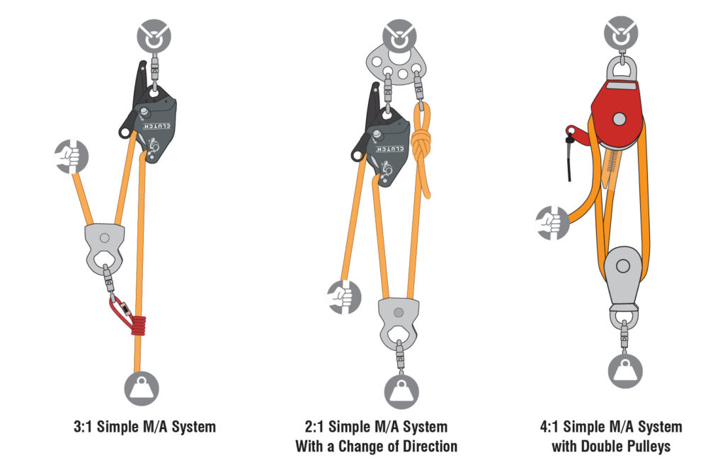
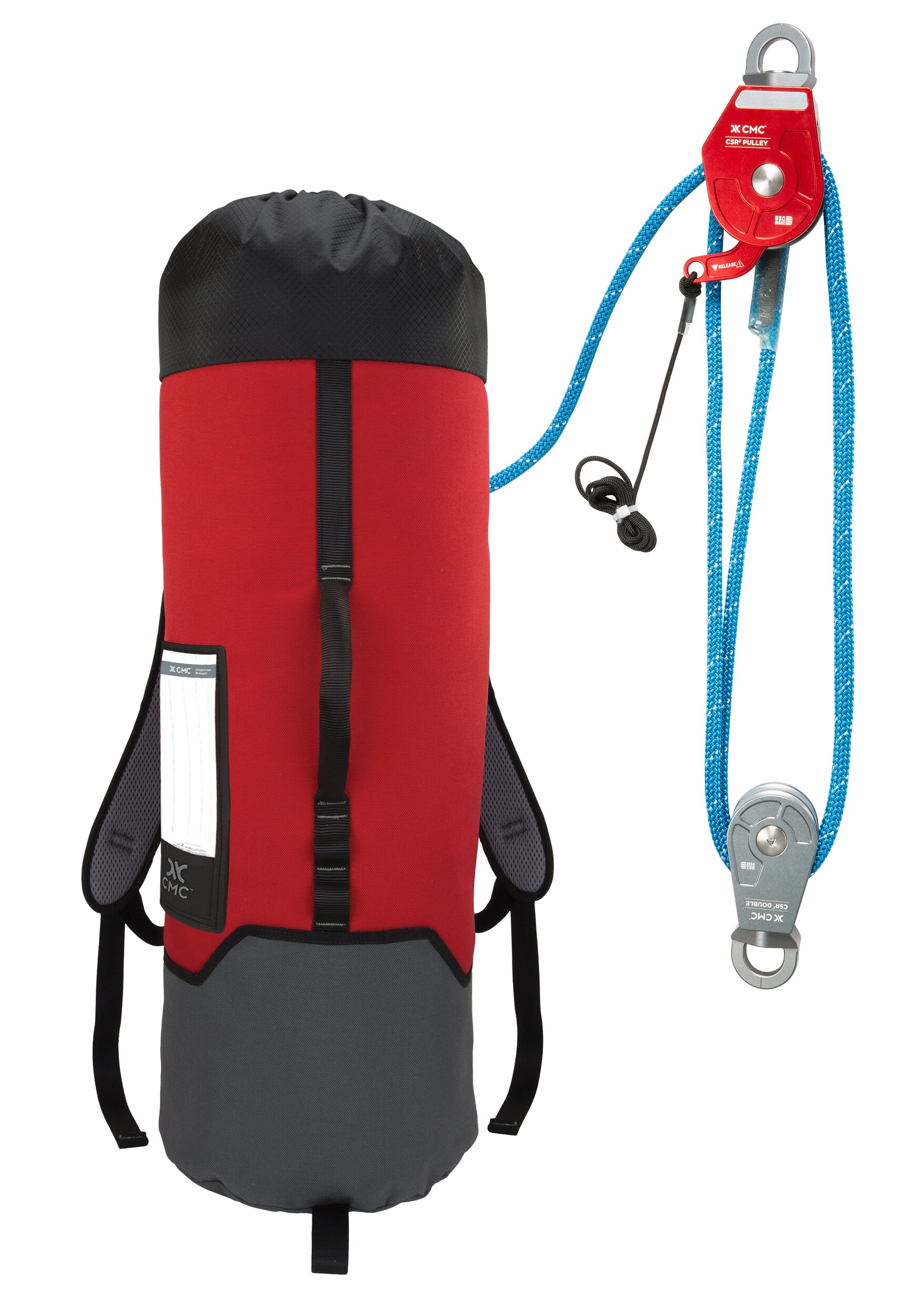
Many confined space operations require a vertical entry. When we build a mechanical advantage system to move a load in this situation, a simple “Block and Tackle” system such as a 2:1 “Ladder Rig” or a 4:1 with double sheave pulleys at the top and bottom can be used.
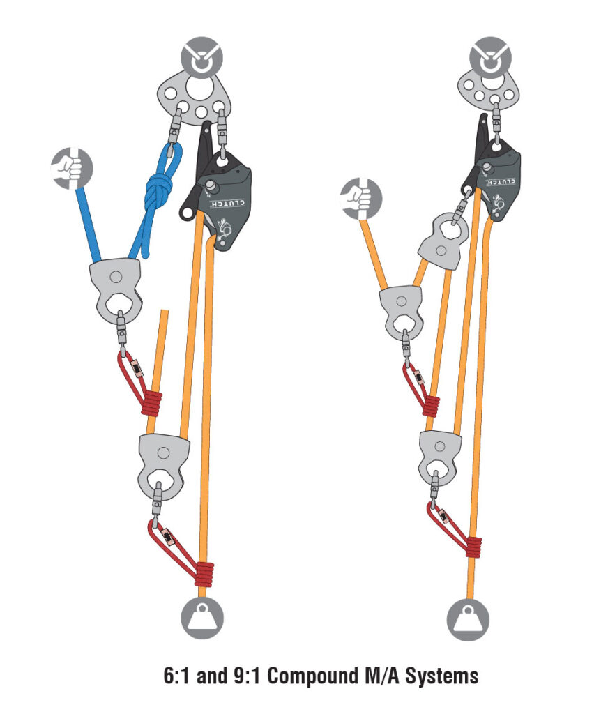
Compound Pulley Systems
Compound pulley systems are created when a simple pulley system is pulling on another simple pulley system. By adding a 2:1 mechanical advantage to a 3:1 mechanical advantage system you compound, or multiply, the mechanical advantage and end up with a 6:1. A 3:1 pulling on another 3:1 gives you a mechanical advantage of 9:1.
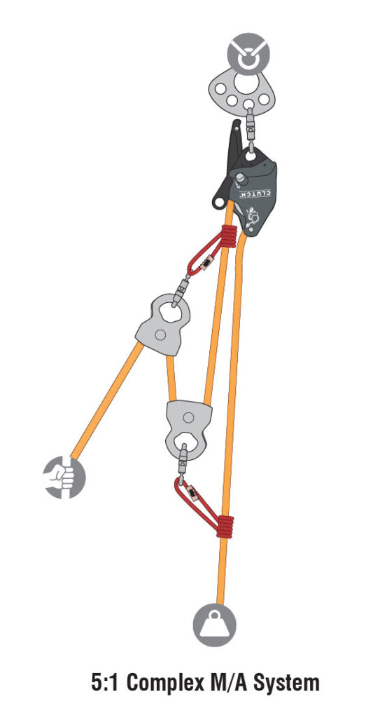
Complex Pulley Systems
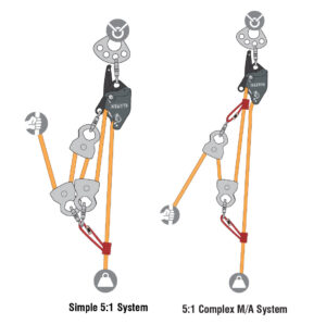
A system that is neither simple nor compound is a complex pulley system. The 5:1 shown is a complex system.
As the mechanical advantage increases, the amount of rope that must be pulled through the system also proportionally increases. With this in mind, it is best to use as little mechanical advantage as possible to complete the task. A simple 1:1 with a change of direction and a ratchet, with enough manpower to pull the load, will usually get the job done quicker. When a manpower shortage becomes the problem, increase the mechanical advantage.
A complex pulley system is generally more efficient than the equivalent simple pulley system. For instance, a complex 5:1 requires 1 less pulley giving the system less friction than a simple 5:1. In addition, a complex 5:1 only requires 4 ft of rope to be pulled through the system to raise the load 1 ft, as opposed to a simple 5:1 that requires 5 ft of rope to be pulled to raise the load 1 ft.
Piggyback Systems
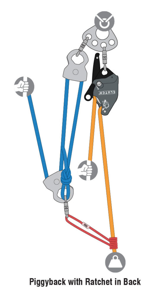
Another method that can be used is a “piggyback”, which is a mechanical advantage system on a haul line. The load is supported on a separate rope held by a ratchet, and a pre-rigged mechanical advantage system is connected to the haul line with a prusik hitch when the load needs to be raised. This can be helpful in situations where the load is raised and lowered back and forth several times. Piggyback systems can be of any level of mechanical advantage. While not common, piggyback lowering systems can also be rigged. They are usually used for short distances or when passing a knot.
The T-Method
Determining the mechanical advantage of pulley systems can be accomplished in several ways. Most are specific to one type of system. The T–Method works for all systems and provides other important information such as the maximum force applied to each component of the system. It works by determining the units of tension on each segment of rope in the system. The actual value of 1 unit of tension varies as the actual input and output forces change. The minimum unit of tension is determined by the load being hauled and by the mechanical advantage of the system. The maximum unit of tension is determined by the maximum input force applied to the system. The input force is determined by the number of haulers on the haul team and how hard they pull.
Applying the T-Method to a Simple Mechanical Advantage System
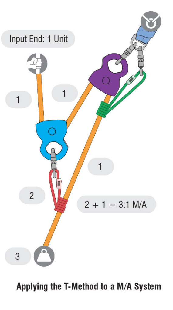
To determine theoretical mechanical advantage using the T-method, start at the input end with 1 unit of tension as seen in the image above. Each pulley will achieve equilibrium, so 1 unit will enter the blue pulley and 1 unit will exit the pulley. At the point where the carabiner attaches to the blue pulley to the red prusik (also known as the apex of the pulley), there would be 2 units of tension. Those 2 units of tension are applying force to the red prusik. Now, back to the rope that just exited the blue pulley, that unit of tension travels into the purple pulley mounted at the anchor. Again, 1 unit of tension enters the pulley, and 1 exit, leaving 2 units of tension on the anchor. The one unit of tension that exits the purple pulley then travels down the rope and meets up with the 2 units of tension at the prusik. Add these together to get 3 units of tension, making this a 3:1. Going back to the definition of a simple system, we see that the one moving pulley is moving in the same direction as the load, making this a simple 3:1 system.
Let’s look at this again with actual weight. Assume we have a 3 kN load or output force. If you take 3kN and divide by 3 you get 1kN. 1kN of force is needed at the input end. 1kN enters the MA pulley and 1 kN exits the pulley, placing 2 kN of force on the apex of the pulley, the carabiner, and the prusik. Now, back to the 1 kN that just exited the pulley, that 1 kN of force travels into the pulley mounted at the anchor and 1 kN of force and 1 kN exits, placing 2 kN of force on the anchor when the load is being raised. The 1 kN of force exiting the pulley then travels down the rope and meets up with the 2 kN of force at the prusik, for a total of 3 kN of the load.
In subsequent posts, we will factor in pulley friction to determine actual mechanical advantage.
To learn more about how to calculate mechanical advantage, check out our Technician Manuals, eBook, or our Free CMC field guide app:
Rope Rescue Technician Manual

eBook: Rope Rescue Technician Manual
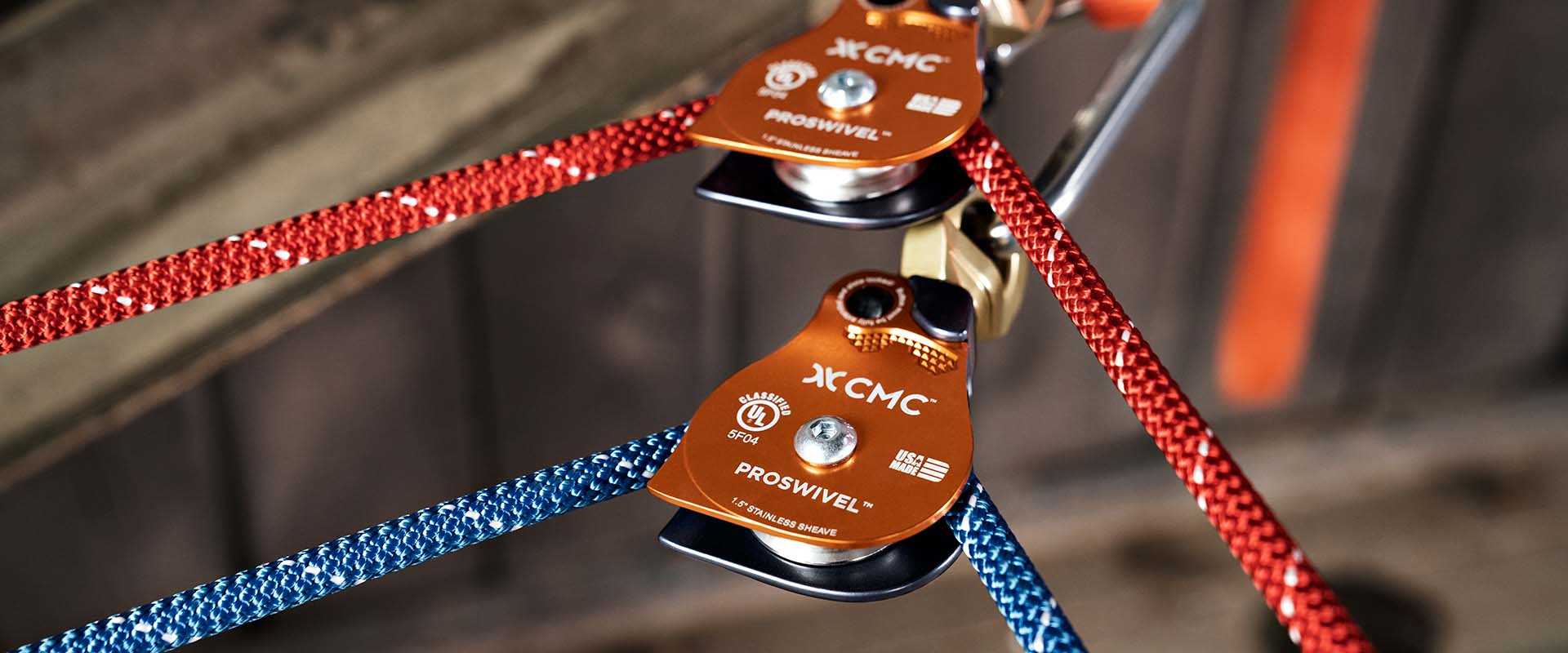
CMC ProSwivel™ Pulleys

Confined Space Rescue Technician Manual